|
Manipulator Kinematics
Matrix Description of Position
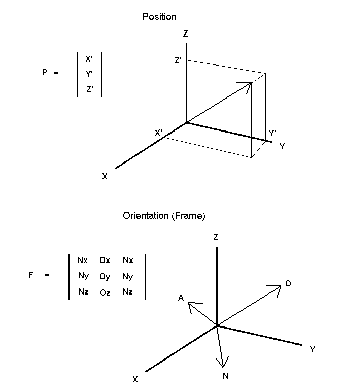
A single point in space can be described by a single column/three row matrix, which contains the three variables x, y and z. Each of these variables represents a single axis of a three-dimensional coordinate system. The orientation of an object, also referred to as a frame, can be described by a three column/three row matrix set at the origin of an X-Y-Z three dimensional coordinate system.
|
|
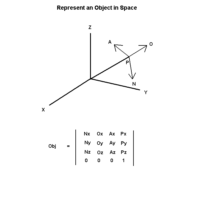
An object can be completely described in space by describing the position of the origin of a frame (a vector) and describing the orientation of that frame.
N, O, and A are three unit vectors of orientation. P is a vector describing the orientation of the frame. The bottom row, consisting of three zeros followed by a one, is added to make a square, or homogeneous, matrix:
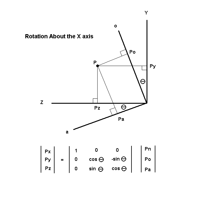
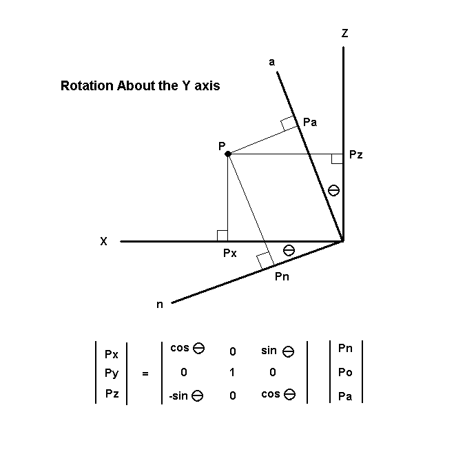
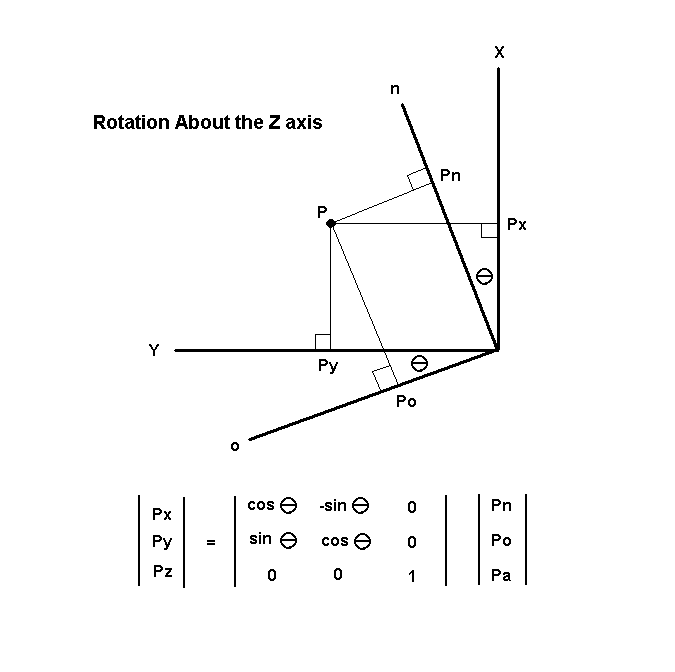
A single reference plane contained in one plane of a three dimensional coordinate system can be rotated about a perpendicular axis by multiplying by an appropriate three by three matrix:
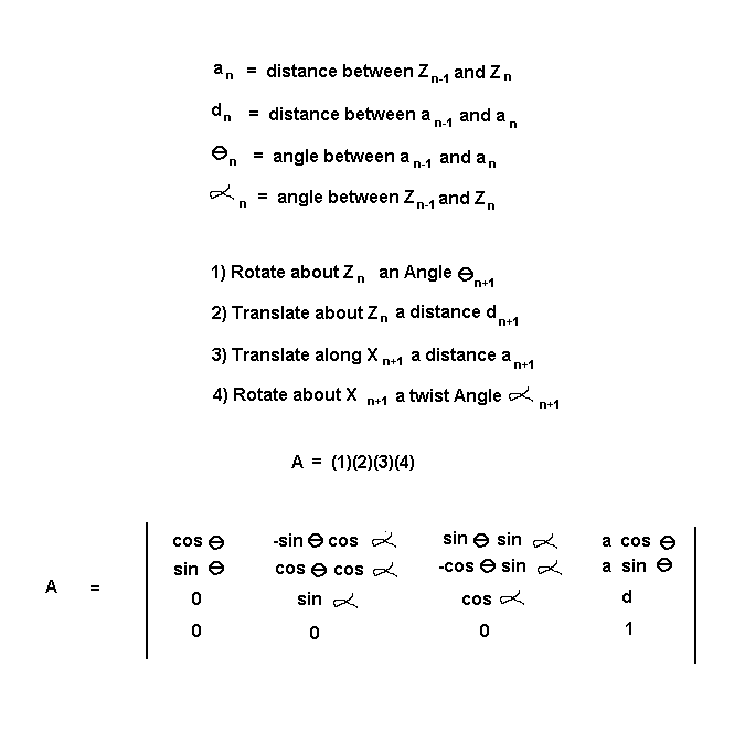
In 1955, a convention was developed for assigning coordinate frames in a manipulator, which contains a chain of joints. The chain is partitioned into its constituent links. Each link is characterized by four link parameters. These link parameters are inserted into a corresponding 'A' matrix. The 'A' matrices are multiplied in sequence to calculate the end effector position. This process is known as forward kinematics. The kinematic variables were determined for this manipulator. The following pages describe the process in graphical form.
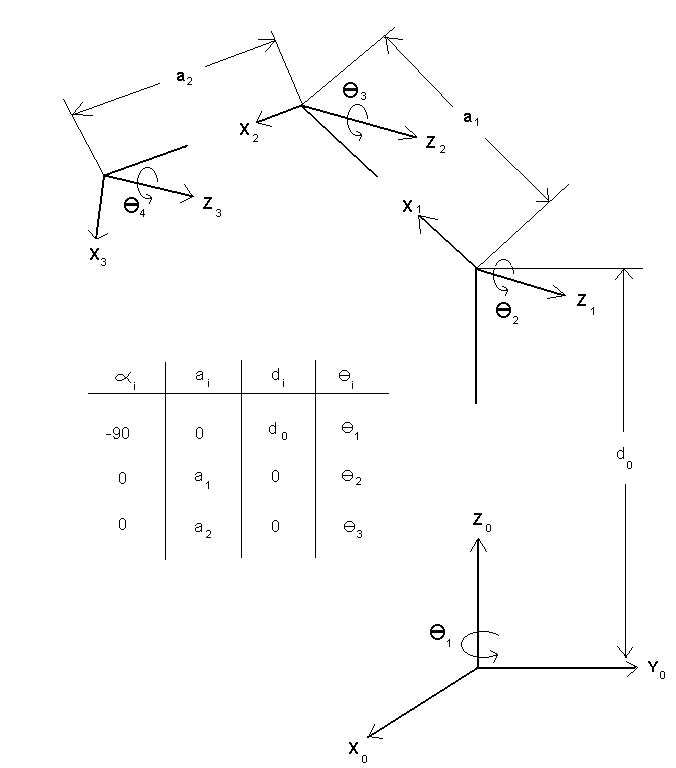
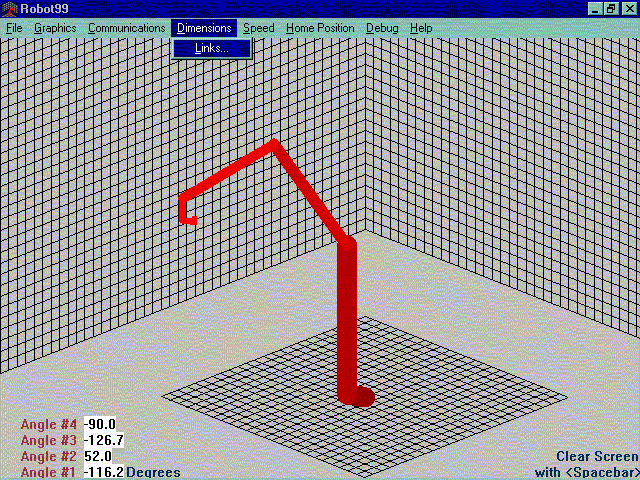
Here is an example of a 4 degree-of-freedom manipulator:
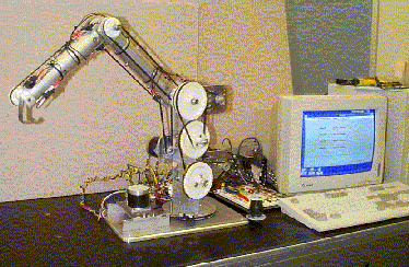
Here is an example of an actual manipulator built to the above specifications. This manipulator is designed to handle a tray of silicon wafers in cleaning operations:
|


